


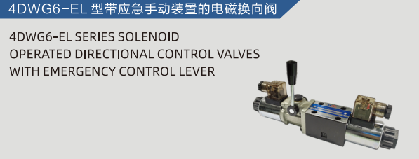
DIRECTIONAL CONTROL VALVES are essential components in hydraulic and pneumatic systems. They precisely manage fluid flow, directing it to specific actuators or sections of a circuit. For instance, the 4DWG6-EL model from hanshang hydraulics exemplifies advanced control, ensuring reliable operation in various applications. These valves open, close, or redirect fluid paths, making automated machinery function effectively.
Key Takeaways
- Directional control valves guide fluid in machines. They start, stop, or change how parts move.
- Valves come in many types. They differ by how many connections they have and how many ways they can direct fluid.
- Choosing the right valve is important. It makes sure machines work well and last a long time.
Fundamental Principles of DIRECTIONAL CONTROL VALVES
Core Components of Directional Control Valves
Directional control valves, essential for managing fluid power, consist of several critical components working in concert. The robust valve body forms the primary enclosure. It houses all internal mechanisms and provides precisely machined ports for fluid connections. These ports include a pressure port (P) for incoming fluid, tank ports (T) for fluid return, and work ports (A, B) that connect to actuators. Inside this body, a movable element, either a cylindrical spool or a conical poppet, dictates the fluid’s path. This element slides or lifts to open and close specific internal passages. An actuator supplies the necessary force to move the spool or poppet. Actuation methods vary widely, including manual levers, electrical solenoids, hydraulic pilot signals, or mechanical linkages. Often, springs are integrated to return the internal element to a predetermined neutral or default position when the actuator is released.
Basic Operation of Directional Control Valves
The operational principle of these valves is quite intuitive. High-pressure fluid enters the valve through a designated pressure port. When an operator or an automated control system activates the valve’s actuator, it initiates the precise movement of the internal spool or poppet. This shift within the valve body reconfigures the internal flow paths. The reconfigured paths then direct the incoming fluid from the pressure port to a specific work port, typically labeled ‘A’ or ‘B’. Concurrently, the opposing work port connects to the tank port, allowing fluid to return to the system’s reservoir. This controlled redirection of fluid flow effectively starts, stops, or reverses the motion of connected hydraulic or pneumatic actuators, such as cylinders or motors. This fundamental action allows for precise control over machinery.
Classifying DIRECTIONAL CONTROL VALVES by Ports and Positions
Understanding Port and Position Configurations
Engineers classify directional control valves primarily by their number of ports and positions. This classification system provides a clear, standardized way to describe a valve’s function and capabilities within a hydraulic or pneumatic circuit. Ports represent the connection points for fluid lines. These include the pressure inlet (P), tank or exhaust outlets (T or R), and work ports (A, B) that connect to actuators. Positions refer to the distinct flow paths the valve’s internal element can create. Each position dictates a unique configuration of fluid connections between the ports. For instance, a valve with two positions can either be open or closed, or it can direct fluid in one of two ways. The combination of ports and positions defines how a valve controls fluid flow and, consequently, the movement of an actuator.
2/2 Way Directional Control Valves
A 2/2 way directional control valve features two ports and operates in two positions. This valve type functions as a simple on/off switch for fluid flow. In its first position, the valve allows fluid to pass from the inlet port to the outlet port. In its second position, the valve completely blocks the flow. These valves are ideal for basic isolation or shut-off applications where fluid needs to be either fully supplied or completely stopped. Common uses include controlling the flow to a single-acting cylinder or isolating a section of a hydraulic circuit.
3/2 Way Directional Control Valves
A 3/2 way directional control valve has three ports and two positions. This configuration typically includes a pressure port (P), a work port (A), and a tank or exhaust port (T). In one position, the valve connects the pressure port to the work port, allowing fluid to flow to an actuator. Simultaneously, it blocks the work port from the tank port. In the second position, the valve blocks the pressure port and connects the work port to the tank port, allowing fluid from the actuator to return to the reservoir or exhaust. This valve type commonly controls single-acting cylinders, extending them with pressure and retracting them by venting fluid.
4/2 Way Directional Control Valves
A 4/2 way directional control valve incorporates four ports and two positions. These valves are essential for controlling double-acting cylinders or reversing the direction of hydraulic motors. The four ports typically consist of a pressure port (P), two work ports (A and B), and a tank or exhaust port (T). In its first position, the valve directs fluid from P to A, while simultaneously connecting B to T. This action might extend a cylinder. In the second position, the valve reverses the flow, connecting P to B and A to T, which would retract the cylinder. This design provides straightforward, reversible control for actuators.
4/3 Way Directional Control Valves
A 4/3 way directional control valve offers four ports and three positions. This valve type provides more versatile control than its 4/2 counterpart due to the addition of a neutral, or center, position. The four ports are P, A, B, and T. The two outer positions function identically to a 4/2 valve, directing fluid to extend or retract a double-acting cylinder. The crucial third, or center, position allows for various control options when the actuator is not moving.
- Closed Center: All ports are blocked in the neutral position. This holds the actuator in a fixed position and conserves energy by blocking pump flow.
- Open Center: P, A, B, and T ports are all connected in the neutral position. This allows fluid to circulate freely back to the tank, reducing heat buildup but not holding the actuator.
- Tandem Center: P is connected to T, while A and B are blocked. This allows pump flow to return to the tank at low pressure, while holding the actuator in position.
These neutral positions offer flexibility for stopping, holding, or floating actuators in complex systems.
5/2 Way Directional Control Valves
A 5/2 way directional control valve features five ports and two positions. These valves are particularly common in pneumatic systems for controlling double-acting cylinders. The five ports include a pressure inlet (P), two work ports (A and B), and two separate exhaust ports (R1 and R2). In the first position, the valve connects P to A, while B exhausts through R2. In the second position, P connects to B, and A exhausts through R1. The separate exhaust ports allow for independent control of exhaust flow, which can be useful for speed control of the cylinder’s movement in each direction.
5/3 Way Directional Control Valves
A 5/3 way directional control valve combines five ports with three positions, similar to the 4/3 valve but with separate exhaust ports. This valve type is also prevalent in pneumatic applications for double-acting cylinders requiring a neutral holding or floating state. The five ports are P, A, B, R1, and R2. The two outer positions provide the standard extend and retract functions. The central neutral position offers various configurations:
- Closed Center: All ports are blocked, holding the cylinder in place.
- Open Center: All ports are connected, allowing the cylinder to float freely.
- Pressure Center: P is connected to A and B, while R1 and R2 are blocked, applying pressure to both sides of the cylinder.
This versatility makes 5/3 way valves suitable for applications demanding precise control over cylinder movement and intermediate stopping.
Internal Designs of DIRECTIONAL CONTROL VALVES
The internal design of a valve dictates its performance and suitability for specific applications. Engineers classify these designs based on the movable element that controls fluid flow. Understanding these internal structures helps in selecting the correct valve for a hydraulic or pneumatic system.
Spool Type Directional Control Valves
Spool type valves are very common in fluid power systems. They feature a cylindrical spool that slides precisely within a machined bore inside the valve body. The spool has lands and grooves. Lands block flow paths, while grooves allow fluid to pass. As the spool moves, it aligns these lands and grooves with various ports, directing fluid to different parts of the circuit. This design offers smooth operation and good flow control. Many industrial applications rely on spool valves for their versatility and reliability.
Poppet Type Directional Control Valves
Poppet type valves use a poppet, which is often a conical or ball-shaped element. This poppet seals directly against a valve seat. When the poppet lifts from its seat, it opens a flow path. When it presses against the seat, it creates a tight seal, blocking fluid flow. Poppet valves are known for their excellent leak-tightness in the closed position. They are often used in applications where zero leakage is critical, such as safety circuits or holding applications. Their simple design also contributes to their robustness.
Rotary Type Directional Control Valves
Rotary type valves contain a rotating element, often a disc or cylinder. This element turns within the valve body. The rotation aligns internal passages and ports, thereby directing fluid flow. As the rotary element turns, it connects different inlet and outlet ports. This design allows for multiple flow paths and can handle various positions. Rotary valves find use in applications requiring sequential operations or where a compact design is beneficial. They provide a distinct method for fluid control compared to sliding or lifting mechanisms.
Actuation Methods for DIRECTIONAL CONTROL VALVES
The method used to shift a valve’s internal element significantly impacts its application and control system. Various actuation methods provide different levels of control, response, and power. Engineers select an actuation method based on system requirements, environmental conditions, and desired automation level.
Manual Actuation of Directional Control Valves
Manual actuation offers direct human control over the valve’s operation. Operators use levers, push buttons, or foot pedals to physically move the spool or poppet. This method provides immediate feedback and simple control. Manual valves are common in applications where an operator needs direct interaction with the machine, such as forklifts or small presses. They are reliable and do not require external power sources for their basic function.
Solenoid Actuation of Directional Control Valves
Solenoid actuation uses electrical signals to control the valve. An electrical current energizes a coil, creating a magnetic field. This field pulls a plunger, which then shifts the valve’s internal element. Solenoid-operated DIRECTIONAL CONTROL VALVES are prevalent in automated systems. They allow for remote control and integration with programmable logic controllers (PLCs). This method offers fast response times and precise control in complex machinery.
Pilot Actuation of Directional Control Valves
Pilot actuation employs fluid pressure to shift the main valve’s internal element. A smaller pilot valve controls the flow of pilot fluid, which then acts on a piston or diaphragm within the main valve. This pressure moves the larger spool or poppet. Pilot actuation is ideal for large valves requiring significant force to shift. It also allows for remote control, especially in hazardous environments, by separating the control signal from the main power flow.
Mechanical Actuation of Directional Control Valves
Mechanical actuation involves physical contact to shift the valve. Cams, rollers, plungers, or springs directly interact with the valve’s operating mechanism. This method often links valve operation to the physical movement of another machine component. For example, a limit switch or a moving part of a conveyor system can mechanically actuate a valve. Mechanical actuation provides a robust and simple control solution for specific sequential operations.
Center Configurations of DIRECTIONAL CONTROL VALVES
The center configuration of a multi-position valve, particularly 4/3 and 5/3 types, defines its behavior when the valve is in its neutral or unactuated state. This central position significantly impacts system performance, energy consumption, and actuator control. Engineers select specific center configurations based on application requirements. These configurations determine how the pump flow and actuator ports connect or block when the valve is not actively directing fluid.
Open Center Directional Control Valves
Open center valves connect all ports (P, A, B, T) in their neutral position. This configuration allows pump flow to return directly to the tank at low pressure. It prevents pressure buildup in the system when the valve is not actuated. This design helps reduce heat generation and saves energy. Actuators connected to an open center valve can float freely when the valve is in its neutral state.
Closed Center Directional Control Valves
Closed center valves block all ports (P, A, B, T) in their neutral position. This configuration holds actuators rigidly in place. It prevents any fluid movement to or from the actuator. When using a closed center valve, the pump flow is blocked. Therefore, systems often require a pressure-compensated pump or a relief valve to manage the blocked flow and prevent excessive pressure.
Tandem Center Directional Control Valves
Tandem center valves offer a unique combination of features. In their neutral position, they connect the pressure port (P) to the tank port (T). This allows pump flow to return to the tank at low pressure, similar to an open center. However, tandem center valves block the work ports (A and B). This design holds the actuator in a fixed position while allowing the pump to unload.
Float Center Directional Control Valves
Float center valves block the pressure port (P) in their neutral position. They connect both work ports (A and B) to the tank port (T). This configuration allows the actuator to move freely under external forces. For example, a hydraulic cylinder can extend or retract as a load pushes or pulls it. This “floating” capability is useful in applications where an implement needs to follow ground contours.
Selecting the Right DIRECTIONAL CONTROL VALVE
Choosing the correct directional control valve is a critical step in designing any fluid power system. The right selection ensures optimal performance, efficiency, and longevity of the machinery. Engineers must carefully evaluate several factors to match the valve’s capabilities with the application’s specific demands. This thoughtful process prevents operational issues and maximizes system reliability.
Key Selection Criteria for Directional Control Valves
Engineers consider many factors when selecting a directional control valve. First, they determine the valve’s primary function. Does the system need simple on/off control, or does it require precise positioning of an actuator? Second, they assess the required performance characteristics. This includes how quickly the valve must respond and how much fluid it needs to handle. Third, cost and availability play a role in the decision. Finally, environmental conditions and specific application requirements also influence the final choice.
Flow Rate and Pressure Considerations
Flow rate and pressure are fundamental hydraulic parameters. The valve’s maximum flow rate must accommodate the system’s fluid volume requirements. An undersized valve restricts flow, causing pressure drops and heat generation. An oversized valve can lead to sluggish response and unnecessary cost. Similarly, the valve’s pressure rating must exceed the system’s maximum operating pressure. This ensures safe operation and prevents component failure. Designers also consider pressure drop across the valve. Excessive pressure drop wastes energy and reduces system efficiency.
Response Time and Cycle Speed Requirements
Response time refers to how quickly a valve shifts from one position to another. Applications requiring rapid actuator movement demand valves with fast response times. For example, high-speed manufacturing processes often need quick-acting valves. Cycle speed indicates how frequently a valve operates within a given period. Valves in continuously cycling applications must withstand high fatigue. Their design must ensure durability over many operations. Solenoid-operated valves generally offer faster response than manual or pilot-operated types.
Environmental and Application Factors
The operating environment significantly impacts valve selection. Extreme temperatures, both ambient and fluid, require valves made from suitable materials. Contamination levels in the fluid dictate the need for specific filtration and valve designs. For instance, poppet valves tolerate dirt better than spool valves. Vibration and shock resistance are crucial for mobile equipment or heavy industrial machinery. Mounting options, such as subplate or manifold mounting, affect system layout and maintenance. Finally, specific industry standards, like those for food processing or hazardous locations, impose additional requirements on valve construction and certification.
Advanced DIRECTIONAL CONTROL VALVE Technologies
Modern fluid power systems demand greater precision and efficiency. Advanced DIRECTIONAL CONTROL VALVES meet these needs. These specialized valves offer capabilities beyond basic on/off control. They provide fine-tuned regulation of fluid flow and pressure.
Proportional Directional Control Valves
Proportional directional control valves offer variable control over fluid flow. Unlike standard on/off valves, they can adjust the flow rate continuously. An electrical input signal, often from a controller, dictates the spool’s position. This allows for precise control of actuator speed and position. Industries use these valves in applications requiring smooth acceleration, deceleration, and accurate positioning. Examples include material handling and machine tool operations.
Servo Directional Control Valves
Servo directional control valves represent the pinnacle of precision. They provide extremely accurate and dynamic control of fluid flow. These valves operate within a closed-loop system. A feedback mechanism constantly monitors the actuator’s position or velocity. The valve then adjusts fluid flow to correct any deviations from the desired command. Servo valves offer very fast response times and high resolution. Engineers employ them in demanding applications like flight simulators, robotics, and test stands.
Cartridge Directional Control Valves
Cartridge directional control valves offer a compact and modular design. Manufacturers insert these valves into a manifold block. This design eliminates external piping between individual valve components. Cartridge valves save space and reduce potential leak points. They also simplify system assembly and maintenance. Their modularity allows designers to create complex hydraulic circuits efficiently. These valves find widespread use in mobile equipment, industrial machinery, and custom hydraulic power units.
Real-World Applications of DIRECTIONAL CONTROL VALVES
DIRECTIONAL CONTROL VALVES are indispensable components across numerous industries. They enable precise movement and operation in a vast array of machinery. These valves translate control signals into physical actions, making complex systems function seamlessly.
Industrial Automation with Directional Control Valves
In industrial automation, these valves play a crucial role. They manage the flow of hydraulic or pneumatic fluid to actuators in manufacturing plants. For example, robotic arms use them to control gripper movements and joint articulation. Presses rely on them for precise ram extension and retraction. Assembly lines utilize them to position components accurately. This precise control ensures efficient and repeatable production processes.
Mobile Hydraulics and Directional Control Valves
Mobile equipment heavily depends on these valves for operational control. Construction machinery like excavators and bulldozers use them to operate their booms, buckets, and blades. Agricultural tractors employ them for lifting and lowering implements. Forklifts utilize them to raise and tilt loads. These applications demand robust valves that can withstand harsh environments and provide reliable performance.
Aerospace and Marine Directional Control Valves
The aerospace and marine sectors also extensively use these critical components. In aircraft, they control landing gear deployment, flap movement, and steering systems. Marine vessels use them for rudder control, anchor winches, and cargo handling systems. The high-stakes nature of these environments requires valves with exceptional reliability, precision, and durability. Engineers select these valves for their ability to perform under extreme conditions and ensure safety.
The Future of DIRECTIONAL CONTROL VALVES in 2026
The fluid power industry continues its rapid evolution. Innovations in technology will significantly reshape the design and function of DIRECTIONAL CONTROL VALVES by 2026. These advancements aim to enhance performance, efficiency, and integration within complex systems.
Smart Directional Control Valves and IoT Integration
Future valves will feature embedded sensors and advanced communication capabilities. These “smart” valves will collect real-time operational data. They will transmit this information to central control systems or cloud platforms via the Internet of Things (IoT). This integration enables predictive maintenance, allowing systems to anticipate failures before they occur. It also facilitates remote monitoring and diagnostics, optimizing system uptime and performance. Operators will gain unprecedented insight into valve health and fluid dynamics.
Energy Efficiency in Directional Control Valves
Manufacturers will prioritize energy efficiency in upcoming valve designs. New materials and optimized internal geometries will reduce pressure drops and minimize power consumption. Proportional and servo valves will offer even finer control, preventing unnecessary energy waste. These advancements contribute to more sustainable hydraulic and pneumatic systems. They also help industries meet increasingly stringent environmental regulations.
Miniaturization and Modularity of Directional Control Valves
The trend towards smaller, more compact machinery drives miniaturization in valve technology. Future valves will occupy less space while maintaining or improving performance. Modular designs will also become more prevalent. These allow for easier assembly, configuration, and replacement of valve components. This modularity simplifies system design and reduces maintenance time. It offers greater flexibility for diverse application requirements.
This guide explored DIRECTIONAL CONTROL VALVES, from basic 2/2 way types to advanced proportional and servo models. Proper valve selection is crucial for system efficiency and reliability. Future innovations promise smarter, more energy-efficient, and miniaturized valve technologies.
FAQ
What is the primary purpose of a directional control valve?
A directional control valve manages fluid flow. It directs fluid to specific actuators. This action starts, stops, or reverses motion in hydraulic or pneumatic systems. Gear
What distinguishes a 4/2 way valve from a 4/3 way valve?
A 4/2 way valve has four ports and two positions. It provides on/off control. A 4/3 way valve adds a third, neutral position. This allows for stopping or holding an actuator.
Why do automated systems often use solenoid-actuated valves?
Solenoid valves use electrical signals for control. They offer fast response times and remote operation. This makes them ideal for integration with PLCs in automated machinery.