


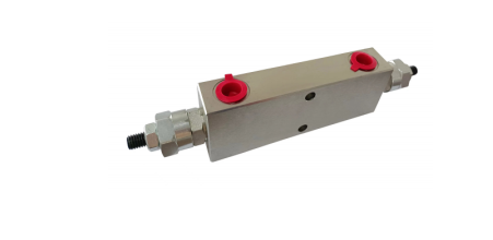
A HYDRAULIC COUNTERBALANCE VALVE prevents uncontrolled movement or “runaway” of a hydraulic actuator under an overrunning load. It maintains a set back pressure. This ensures smooth, controlled motion and prevents cavitation, making it essential for safety and precise operation in many HYDRAULIC VALVES systems.
Key Takeaways
- Hydraulic counterbalance valves stop hydraulic parts from moving too fast. They keep things safe and working smoothly.
- These valves create pressure to control movement. This stops parts from dropping or speeding up on their own.
- Choosing the right valve is important. It depends on how the machine works and what it needs to do.
The Fundamental Role of HYDRAULIC COUNTERBALANCE VALVEs in Hydraulic Systems
Hydraulic systems rely on precise control and safety. HYDRAULIC COUNTERBALANCE VALVEs play a crucial role in achieving these objectives. They manage the forces acting on hydraulic actuators, ensuring predictable and safe operation.
Preventing Overrunning Loads and Cavitation
Overrunning loads occur when an external force, such as gravity, attempts to move a hydraulic actuator faster than the pump can supply fluid. This situation can lead to uncontrolled movement, often called “runaway.” A HYDRAULIC COUNTERBALANCE VALVE actively prevents this by creating a controlled back pressure. This back pressure resists the external force, ensuring the actuator moves only when the system actively commands it. Without this resistance, the actuator could accelerate rapidly, causing damage or injury. Furthermore, overrunning loads can create a vacuum or low-pressure condition on the return side of the actuator. This vacuum leads to cavitation, where air bubbles form and collapse, causing noise, vibration, and significant damage to hydraulic components. The constant back pressure maintained by the counterbalance valve keeps the return line pressurized, effectively preventing cavitation and extending the lifespan of the system.
Ensuring Smooth and Controlled Actuator Movement
Achieving smooth and precise motion is critical in many hydraulic applications, from cranes to excavators. The counterbalance valve ensures this by modulating the flow out of the actuator. When an actuator lowers a heavy load, for example, the valve restricts the oil flow, preventing the load from free-falling. This controlled restriction allows the operator to maintain a consistent lowering speed, regardless of load variations. The valve continuously adjusts its opening based on the pressure differential, providing a damping effect. This damping eliminates jerky movements and oscillations, which improves operational efficiency and the quality of work performed by the machine.
Enhancing Safety and System Stability
The primary function of a counterbalance valve directly contributes to enhanced safety and overall system stability. By preventing uncontrolled actuator movement, it protects both personnel and equipment. Operators can confidently maneuver heavy loads, knowing the system will maintain control even if the prime mover loses power or a hose ruptures. In such scenarios, the valve acts as a safety brake, holding the load in position. This inherent stability reduces the risk of accidents, equipment damage, and costly downtime. It ensures that hydraulic machinery operates within its design parameters, promoting a safer working environment and extending the operational life of the entire hydraulic system.
Understanding Single-Acting HYDRAULIC COUNTERBALANCE VALVEs
Description and Basic Operation
A single-acting HYDRAULIC COUNTERBALANCE VALVE manages the movement of single-acting hydraulic cylinders. These cylinders extend under hydraulic pressure and retract due to an external force, often gravity or a spring. The valve installs on the return line of the cylinder. It creates a back pressure. This back pressure prevents the load from free-falling. When the system extends the cylinder, fluid flows freely through the valve’s check valve. When the system retracts the cylinder, the valve restricts the outflow. This restriction ensures a controlled descent. The valve opens only when the pilot pressure, combined with the load pressure, overcomes its spring setting.
Key Characteristics and Applications
Single-acting counterbalance valves feature a straightforward design. They are robust and reliable for specific applications. Their primary characteristic is unidirectional flow control. They allow free flow in one direction and controlled flow in the opposite direction. Common applications include forklift masts, crane booms, and aerial work platforms. These machines often lift heavy loads and rely on gravity for lowering. The valve ensures the load descends at a safe, predictable speed. It prevents sudden drops.
Advantages and Limitations
The main advantage of single-acting counterbalance valves is their simplicity and cost-effectiveness. They provide essential safety and control for single-acting actuators. Their design is less complex than dual-acting versions. However, their primary limitation is their suitability only for single-acting systems. They cannot manage bidirectional flow control. Systems requiring precise control over both extension and retraction movements need different valve types. They also might not offer the same level of fine-tuned control as more advanced pilot-operated valves in certain complex scenarios.
Exploring Dual-Acting HYDRAULIC COUNTERBALANCE VALVEs
Description and Basic Operation
A dual-acting counterbalance valve manages the movement of double-acting hydraulic cylinders. These cylinders extend and retract under hydraulic pressure. The valve connects to both lines of the cylinder. It creates back pressure in both directions of movement. This prevents uncontrolled motion during extension and retraction. When the system extends the cylinder, the valve controls the oil flow from the rod end. When the system retracts the cylinder, it controls the oil flow from the cap end. The valve ensures precise speed control for both directions. It opens only when pilot pressure, combined with load pressure, overcomes its spring setting.
Key Characteristics and Structure
Dual-acting counterbalance valves feature a more complex internal structure than single-acting types. They contain two independent valve sections within a single body. Each section includes a main spool, a pilot piston, and a spring. This design allows the valve to control flow in both directions. It effectively manages overrunning loads regardless of the cylinder’s movement direction. The valve body often includes ports for the cylinder lines and pilot lines. This integrated design simplifies plumbing for double-acting actuators. A HYDRAULIC COUNTERBALANCE VALVE of this type provides robust control.
Advantages and Limitations
Dual-acting counterbalance valves offer significant advantages for systems requiring bidirectional load control. They provide full control over both extension and retraction movements. This ensures consistent speed and prevents runaway conditions in either direction. Their integrated design saves space and simplifies installation compared to using two separate single-acting valves. However, their complexity means higher cost and potentially more maintenance points. They also require careful pressure setting for both directions to ensure optimal performance and prevent system instability.
The Mechanics of Pilot-Operated HYDRAULIC COUNTERBALANCE VALVEs
Description and Basic Operation
Pilot-operated counterbalance valves introduce an external pilot signal. This signal assists the load pressure. It helps open the valve. This design allows for more precise control. It also reduces the required pressure setting. The valve remains closed until the combined force of the load pressure and the pilot pressure overcomes its spring setting. This ensures the actuator holds its position securely. When the system commands movement, the pilot pressure actively helps to open the valve. This provides a controlled descent or retraction.
Key Characteristics and Pilot Ratio Importance
The pilot ratio is a critical characteristic. It defines the relationship between pilot pressure and load pressure. A higher pilot ratio means less pilot pressure is necessary. This opens the valve. It provides greater sensitivity. It also offers finer control over the actuator. Selecting the correct pilot ratio is essential. An incorrect ratio can lead to instability. It can also cause jerky movements. Engineers carefully choose this ratio. They match it to the specific application requirements.
Advantages and Limitations
These valves offer several advantages. They provide enhanced control. They reduce pressure drop. They improve system stability. They ensure more precise load holding. This makes them suitable for applications demanding high accuracy. However, they are more complex. This leads to higher costs. Improper pilot ratio selection can also cause instability. This requires careful design and setup.
Direct-Acting HYDRAULIC COUNTERBALANCE VALVEs Explained
Description and Basic Operation
Direct-acting counterbalance valves function without an external pilot signal. They directly sense the pressure created by the load. This load pressure acts upon the valve’s internal spool. A calibrated spring holds the spool in a normally closed position. When the load pressure surpasses the spring’s preset force, the spool shifts. This action opens a flow path for the hydraulic fluid. The valve then maintains a consistent back pressure. This mechanism effectively prevents uncontrolled movement of the hydraulic actuator. It ensures a smooth, controlled descent or retraction of the load.
Key Characteristics and Simplicity
These valves are notable for their straightforward and robust design. They incorporate fewer internal components compared to more complex valve types. This inherent simplicity enhances their reliability in various operational settings. The valve responds immediately and directly to changes in the load. It does not require additional control lines or intricate plumbing. This characteristic simplifies both installation and maintenance procedures. Their design minimizes potential points of failure.
Advantages and Limitations
Direct-acting valves offer distinct advantages. They are typically more cost-effective to manufacture and purchase. Their simple construction contributes to high reliability and a long service life. They perform well in applications where precise, fine-tuned control is not the absolute priority. However, these valves also present certain limitations. They provide less nuanced control compared to pilot-operated HYDRAULIC COUNTERBALANCE VALVEs. They can also introduce a higher pressure drop across the valve. This potentially reduces overall system efficiency. Furthermore, they exhibit less sensitivity to minor fluctuations in load.
Key Characteristics and Considerations for All HYDRAULIC COUNTERBALANCE VALVEs
Selecting and implementing any HYDRAULIC COUNTERBALANCE VALVE requires careful consideration of several key characteristics. These factors directly influence system performance, safety, and efficiency. Understanding them ensures optimal operation.
Pilot Ratio: Understanding its Impact on Performance
The pilot ratio significantly affects valve performance. It defines the relationship between the pilot pressure and the load pressure required to open the valve. A higher pilot ratio means less pilot pressure is necessary to initiate valve opening. This provides greater sensitivity and finer control over actuator movement. Conversely, a lower pilot ratio requires more pilot pressure. Engineers must select the correct pilot ratio. An incorrect ratio can lead to instability or jerky operation.
Pressure Setting and Adjustment for Optimal Control
Proper pressure setting is crucial for effective load control. The valve’s set pressure determines the back pressure it maintains. This setting must exceed the maximum load-induced pressure. A common guideline suggests setting the valve at 1.3 times the maximum load-induced pressure. For example, if the maximum working pressure is 350 bar, the valve should be set around 270 bar (350 / 1.3). Incorrect settings can cause either uncontrolled movement or excessive power loss.
Flow Capacity and Size Selection for System Requirements
Matching the valve’s flow capacity to the system’s requirements is essential. The valve must handle the maximum expected flow rate without excessive pressure drop. Undersized valves restrict flow, causing heat generation and sluggish operation. Oversized valves may not provide adequate control and can be more expensive. Engineers select the correct valve size based on the actuator’s displacement and desired speed.
Mounting Options: Cartridge, In-line, and Manifold
HYDRAULIC COUNTERBALANCE VALVEs offer various mounting options. Cartridge valves insert into custom manifold blocks. This creates compact and integrated hydraulic circuits. In-line valves connect directly into hydraulic lines with threaded ports. They offer flexibility for existing systems. Manifold-mounted valves bolt onto a manifold block. This provides a clean installation and simplifies plumbing. Each option offers specific advantages for different application layouts and space constraints.
Choosing the Right HYDRAULIC COUNTERBALANCE VALVE for Your Application
Selecting the appropriate HYDRAULIC COUNTERBALANCE VALVE is crucial for system performance, safety, and longevity. Engineers must carefully evaluate several factors to ensure optimal operation. This section guides the selection process.
Assessing Load Characteristics (Overrunning, Static, Dynamic)
The nature of the load significantly influences valve choice. Different load types impose distinct demands on the hydraulic system.
- Overrunning Loads: These loads occur when an external force, often gravity, attempts to move the actuator faster than the pump supplies fluid. Cranes lowering heavy objects or excavators digging downhill experience overrunning loads. The chosen valve must effectively create back pressure to prevent uncontrolled movement. It ensures the load descends at a controlled speed.
- Static Loads: Static loads involve holding an actuator in a fixed position against a constant force. A scissor lift holding a platform at height exemplifies a static load. The valve must provide excellent load holding capabilities, minimizing internal leakage to prevent drift over time.
- Dynamic Loads: Dynamic loads involve rapid changes in force or direction. Impact applications or fast-moving machinery generate dynamic loads. The valve needs a quick response time and smooth transition characteristics to manage these fluctuating forces without causing instability or shock.
Matching System Pressure and Flow Requirements
The hydraulic system’s operating parameters directly dictate the valve’s specifications. Engineers must match the valve to these requirements.
- Pressure Requirements: The valve’s maximum operating pressure rating must exceed the system’s maximum working pressure. This prevents valve failure and ensures safe operation. The valve’s set pressure, typically 1.3 times the maximum load-induced pressure, also requires careful calculation.
- Flow Requirements: The valve must accommodate the maximum expected flow rate from the actuator without excessive pressure drop. An undersized valve restricts flow, generates heat, and slows down the actuator. An oversized valve might not provide adequate control and can be less efficient. Engineers determine the correct flow capacity by considering the actuator’s displacement and the desired operating speed.
Desired Level of Control and Precision
Applications vary widely in their need for precise control. This factor guides the selection between different valve types.
- Basic Load Holding: Some applications primarily require preventing uncontrolled movement and holding a load in place. Direct-acting valves often suffice for these simpler needs. They offer robust performance without complex control mechanisms.
- Fine-Tuned Speed Control: Other applications demand highly accurate and smooth speed regulation, especially during lowering or retraction. Pilot-operated valves excel in these scenarios. Their external pilot signal allows for more sensitive control and smoother transitions. The pilot ratio becomes a critical consideration here, as it directly impacts the valve’s responsiveness and precision. A higher pilot ratio generally offers finer control.
Environmental and Operational Conditions
The environment where the hydraulic system operates also influences valve selection.
- Temperature: Extreme ambient or fluid temperatures can affect valve performance and material integrity. Manufacturers specify operating temperature ranges. Engineers must ensure the chosen valve complies with these limits.
- Contamination: Hydraulic systems can encounter varying levels of fluid contamination. Valves with robust designs and appropriate material choices resist wear and damage from particles.
- Vibration and Shock: Applications involving high vibration or shock loads require valves designed to withstand these stresses. Mounting options and valve construction play a role in durability.
- Mounting Space: Physical space constraints often dictate the preferred mounting option (cartridge, in-line, or manifold). Cartridge valves offer compact integration into custom blocks, while in-line valves provide flexibility for existing plumbing.
- Maintenance and Service Life: Engineers consider the ease of maintenance and the expected service life of the valve. Robust designs and readily available spare parts contribute to lower long-term operational costs.
HYDRAULIC COUNTERBALANCE VALVEs are crucial for hydraulic system safety, precision, and efficiency.
- Understanding their various types and features is vital for optimal design and performance.
- Engineers must carefully consider these factors when selecting and implementing these essential components.
FAQ
What is the primary function of a hydraulic counterbalance valve?
A hydraulic counterbalance valve prevents uncontrolled movement of an actuator under an overrunning load. It maintains a set back pressure. This ensures smooth, controlled motion and prevents cavitation.
Why is the pilot ratio important for these valves?
The pilot ratio determines the sensitivity of the valve. It dictates how much pilot pressure is necessary to open the valve. A correct ratio ensures precise control and stable operation.
Can a single-acting counterbalance valve control a double-acting cylinder?
No, a single-acting counterbalance valve cannot control a double-acting cylinder. It only manages flow in one direction. Double-acting cylinders require a dual-acting counterbalance valve for bidirectional control.