


The COUNTERBALANCE CARTRIDGE VALVE serves as a vital component within hydraulic systems. This specialized valve precisely manages over-running loads, effectively preventing uncontrolled movement. For instance, the HANSHANG HSCBCG model demonstrates its primary role in preventing hydraulic overloads. It ensures both operational safety and precise control.
Key Takeaways
- A counterbalance valve stops heavy loads from falling too fast in hydraulic systems.
- This valve makes hydraulic systems safer by controlling how loads move.
- Properly adjusting the valve helps it work best and prevents problems.
How a COUNTERBALANCE CARTRIDGE VALVE Controls Over-Running Loads
Understanding Over-Running Loads in Hydraulic Systems
Hydraulic systems often encounter situations where a load’s weight or external force attempts to drive an actuator faster than the pump can supply fluid. Engineers refer to these as “over-running loads.” Consider a crane lowering a heavy object or a hydraulic cylinder retracting under the force of gravity. Without proper control, these loads can accelerate uncontrollably, leading to cavitation, system damage, and significant safety hazards. The fluid on the return side of the cylinder can create a vacuum, causing the cylinder to “run away.” Effective management of these forces is crucial for safe and efficient operation.
⚠️ Example: Imagine a forklift mast lowering a heavy pallet. If the hydraulic system lacks adequate control, the pallet’s weight could cause the mast to drop rapidly and uncontrollably, posing a serious risk to personnel and equipment.
COUNTERBALANCE CARTRIDGE VALVE Operation During Lifting
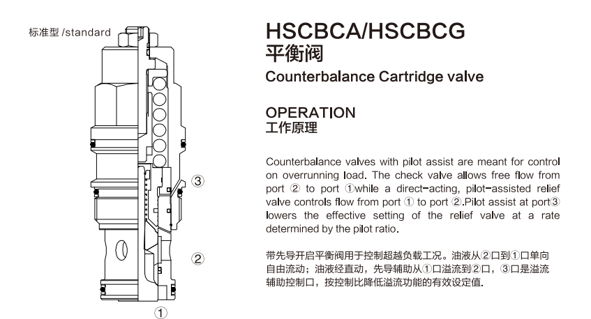
When a hydraulic system lifts a load, the COUNTERBALANCE CARTRIDGE VALVE functions primarily as a check valve. Fluid flows freely from the pump side (port 2) to the actuator (port 1). The valve’s internal check mechanism opens, allowing unrestricted movement of the actuator in the lifting direction. During this phase, the valve does not actively control the load’s speed or position. It simply permits the necessary fluid flow to extend the cylinder or raise the boom.
COUNTERBALANCE CARTRIDGE VALVE Operation During Holding
The COUNTERBALANCE CARTRIDGE VALVE demonstrates its critical load-holding capability when the directional control valve is centered or the pump stops. In this state, the valve closes, effectively blocking the flow of fluid from the actuator (port 1) back to the tank (port 2). This closure prevents the load from drifting or falling due to gravity. The valve’s internal spring and the pressure generated by the load itself keep it securely in place. It acts as a robust mechanical lock, ensuring the load remains stationary until the operator commands movement.
COUNTERBALANCE CARTRIDGE VALVE Operation During Lowering
Lowering an over-running load is where the counterbalance valve truly shines. When the operator commands the load to descend, pilot pressure from the pump side (port 3) acts on the valve’s internal relief mechanism. This pilot pressure proportionally reduces the valve’s set pressure. As a result, the valve opens just enough to allow a controlled amount of fluid to return from the actuator (port 1) to the tank (port 2). The amount of pilot pressure directly dictates the rate of fluid flow, thereby controlling the load’s descent speed. This precise modulation prevents uncontrolled acceleration and cavitation, ensuring a smooth, stable, and safe lowering operation. The valve continuously balances the load’s force against the pilot pressure, maintaining constant control.
Key Functions and Benefits of the COUNTERBALANCE CARTRIDGE VALVE
The COUNTERBALANCE CARTRIDGE VALVE offers numerous advantages in hydraulic systems. It provides essential control and safety features. These valves ensure reliable operation, especially with heavy or over-running loads.
Preventing Uncontrolled Load Movement
The primary function of a counterbalance valve involves preventing uncontrolled load movement. When a load’s weight or external force tries to accelerate an actuator faster than the pump can supply fluid, the valve steps in. It creates a controlled resistance to fluid flow. This resistance ensures the load descends or retracts at a regulated speed. Without this control, loads can “run away,” causing dangerous situations and potential damage to machinery. The valve maintains a constant back pressure on the actuator, effectively holding the load in place until the operator commands movement.
Enhancing Hydraulic System Safety
Counterbalance valves significantly enhance hydraulic system safety. They protect both equipment and personnel from the hazards of uncontrolled load movement. By preventing sudden drops or rapid acceleration, these valves reduce the risk of accidents. They also prevent cavitation, a phenomenon where vacuum pockets form in the hydraulic fluid. Cavitation can severely damage pumps and other components. The valve’s ability to maintain positive pressure on the actuator prevents this destructive condition, ensuring the system operates smoothly and safely.
Providing Thermal Relief and Load Holding
Beyond speed control, counterbalance valves also offer thermal relief and superior load holding. As a load remains stationary, thermal expansion or contraction of the hydraulic fluid can occur. The valve’s internal relief function allows small amounts of fluid to pass, relieving any pressure buildup caused by temperature changes. This prevents damage to the system components. Furthermore, the valve acts as a robust load-holding device. It locks the actuator in position when the directional control valve is neutral. This ensures the load stays exactly where the operator left it, even over extended periods, without drifting.
Distinguishing from Pilot-Operated Check Valves
People sometimes confuse counterbalance valves with pilot-operated check valves, but they serve different purposes. A pilot-operated check valve primarily blocks flow in one direction until a pilot pressure opens it. It acts as a simple lock. A counterbalance valve, however, offers much more sophisticated control. It not only holds a load but also modulates the flow during lowering. This modulation allows for precise speed control of over-running loads. It also provides thermal relief. The counterbalance valve actively manages the load’s descent, whereas a pilot-operated check valve simply opens or closes. This distinction makes the counterbalance valve indispensable for applications requiring fine control over heavy, descending loads.
Practical Applications and Setup of the COUNTERBALANCE CARTRIDGE VALVE
Hydraulic system designers and operators must understand the practical application and setup of these crucial components. Proper installation and adjustment ensure optimal performance and safety.
Proper Adjustment for Optimal Performance
Achieving optimal performance from a COUNTERBALANCE CARTRIDGE VALVE requires precise adjustment. Engineers typically set the valve’s maximum pressure at least 1.3 times the maximum load pressure. This setting ensures the valve can reliably support the load. Manufacturers often provide a factory default setting, usually corresponding to a specific flow rate at the opening pressure. However, operators must fine-tune this setting during system commissioning. They adjust the valve to match the specific load and desired descent speed. Incorrect adjustment can lead to uncontrolled movement or excessive back pressure.
Common Troubleshooting Scenarios
Operators may encounter several common issues with counterbalance valves. If a load descends too quickly or uncontrollably, the valve’s set pressure might be too low. Conversely, if the load moves slowly or with jerky motions, the set pressure could be too high, or the pilot pressure might be insufficient. Contamination within the hydraulic fluid can also cause the valve to stick or operate inconsistently. Technicians should check for proper pilot line connection and ensure the valve is free from debris. Regular maintenance and correct adjustment prevent most operational problems.
Integrating the COUNTERBALANCE CARTRIDGE VALVE into Hydraulic Circuits
Integrating the counterbalance valve into a hydraulic circuit is straightforward. Install the valve directly onto the actuator’s port that experiences the over-running load. For example, place it on the rod side of a cylinder for controlled retraction. The valve’s pilot port connects to the pressure line that extends the actuator. This connection allows the system pressure to pilot the valve open during controlled lowering. This strategic placement ensures the valve effectively manages the load’s movement, providing essential control and safety.
The COUNTERBALANCE CARTRIDGE VALVE plays a critical role in hydraulic system safety. It prevents uncontrolled load movement. This valve ensures precise and controlled load management. Operators achieve smooth, stable operations. It protects both equipment and personnel from potential hazards.
FAQ
What is the primary function of a counterbalance valve?
A counterbalance valve prevents uncontrolled movement of over-running loads. It ensures precise and safe lowering or retraction of hydraulic actuators.
How does a counterbalance valve differ from a standard check valve?
A standard check valve simply blocks flow in one direction. A counterbalance valve actively controls load speed during lowering. It also provides thermal relief.